How to Use a Reverse Socket?
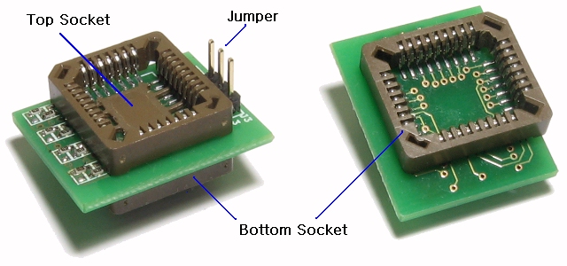
Figure.1 - Layout of the reverse socket
1. Overview of Reverse Socket
A reverse socket is a recovery tool to fix a suface mounted PLCC32 Flashrom without Reworks-tool.
You can fix a suface mounted PLCC32 Flashrom without soldering(or simple soldering with basic tool).
Reverse socket has two mode and three usage according to target application.
※ Definitions:
· Primary flashrom : BIOS flashrom that soldered to motherboard
· Secondary flashrom : A spare flashrom to boot with reverse socket
· Flashrom Swap : Transferring a Primary flashrom interface to Secondary flashrom
· Pin bypass : to disconnect the circuit between existing components and creating a necessary connection
· Pin cutting : to cut a leg of Primary flashrom, it makes a new connection
2. The principle of Reverse Socket
Question : Is it possible to update a Primary flashrom that is direct connected to any programmer?
Answer : No, it is impossible.
As shown below, soldered flashrom is connected to many other unknown device in motherboard.
So, when programmer tries to handle a flashrom, BUS fall in unknown status by these unknown devices.
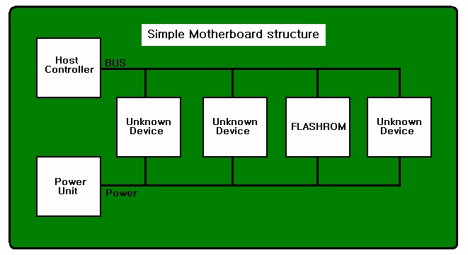
Figure.2 Simple connecting structure of BIOS Flashrom and Motherboard
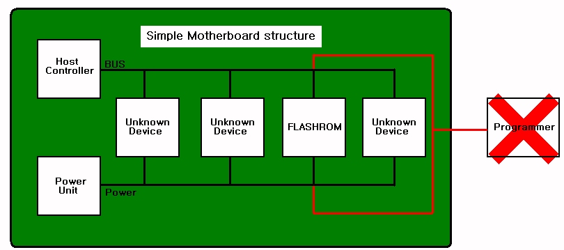
Figure.3 concept - When flashrom was connected directly to programmer
without disconnecting from the motherboard, unintended connection is created.
At worst case, if power is overloaded, motherboad, power unit, programmer, flashrom and on board the various
components (CPU, memory, VGA, Harddisk...) can be breaked.
So, you should never ever try this.
We need a new method, and one of simple method is adding of new flashrom.
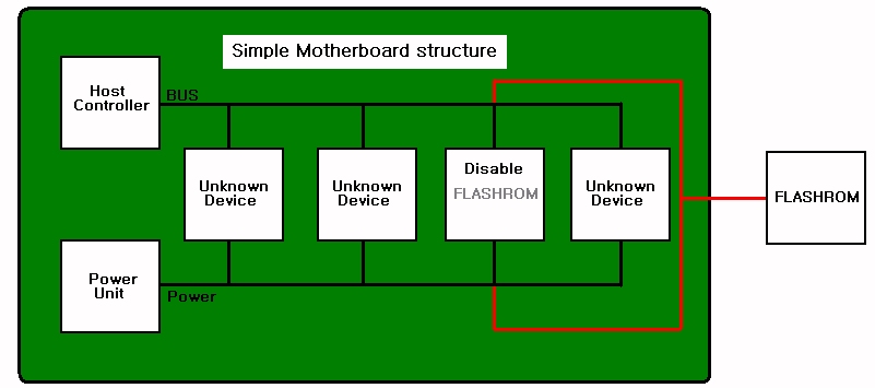
Figure.4 concept - adding of new flashrom, Red-line is reverse socket.
At this case, we have to make the Primary flashrom disable before attaching the Secondary flashrom.
So, reverse socket must have a function that can make Primary flashrom disable.
In this way, motherboard can boot to OS by Secondary flashrom.
After booting, we have to disable Secondary flashrom and enable Primary flashrom in POWER-ON status.
In this status, we can update(or fix) Primary flashrom with BIOS update tool of motherboard manufacture.
(BIOS update tool : AWDFLASH, WINFLASH, PHLASH,AMIFAUTO, FLASH85x, AFUDOS, AFUWIN, UNIFLASH...)
As a result, you can make a status to fix a BIOS with reverse socket.
And you should understand reverse socket has two functions.
· to disable/ebable Primary flashrom and Secondary flashrom.
· to make a connection between Primary flashrom and Secondary flashrom without soldering.
3. Type of Reverse Socket
3.1. FWH/LPC recovery : use when Primary flashrom has FWH / LPC interface
-> See usage.1 and usage.2
feature of usage.1 : depending on motherboard design, does not require a soldering operations.
feature of usage.2 : not depending on motherboard design, needs a Pin-cutting operations.
Rarely, depending on the type of flash ROM may need simple soldering operations.
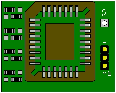
Figure.5 FWH/LPC mode of reverse socket
3.2. Legacy Flashrom recovery : use when Primary flashrom has legacy interface
-> See usage.3
feature - Needs a Pin-bypass operations.
Pin-bypass operations just needs a simple soldering tool.
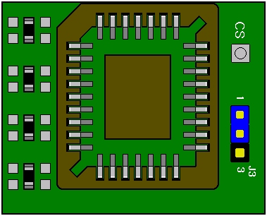
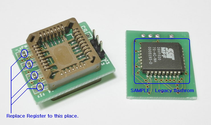
Figure.6 Legacy mode of reverse socket
※ FWH/LPC mode and Legacy mode can be switched by replacing components.
See positions of four chip resistance of left side.
4. Using a Reverse Socket
4.1. usage.1
Parts needed : FWH / LPC mode reverse socket, A secondary flashrom that is same(or compatible) with the Primary flashrom
Conditions of Use :
a. Use only with FWH/LPC flashrom (Wrong usage can break device)
b. Measure resistance next 4 pin(ID0 to ID4) and GND of Primary flashrom.
If all value are under 600Ω, goto usage.2
Any value are over 600Ω, you can go with usage.1
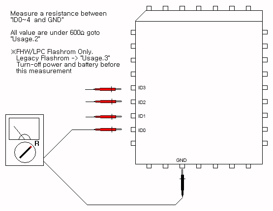
Figure.7 compatibility test
Usage :
a. Write a correct BIOS to Secondary flashrom.
b. Insert Secondary flashrom to Top socket of Reverse socket
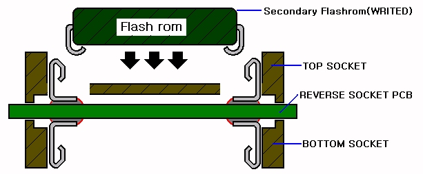
Figure.8 Insert Secondary flashrom to Top socket of Reverse socket
c. Attach Reverse scoket to Primary flashrom on motherboard.
(Warning : Primary flashrom and Secondary flashrom have same direction.)

Figure.9 Attach Reverse scoket to Primary flashrom on motherboard
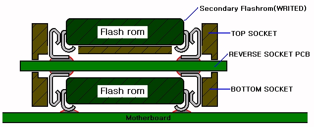
Figure.10 picture attached reverse socket to the primary flashrom
d. to enter into the OS by booting the motherboard.
(recommended to copy a BIOS update tool and BIOS file to harddisk before boot)
e. OS is fully booted and ready to run the BIOS update utility and
Remove the reverse socket from Primary flashrom.
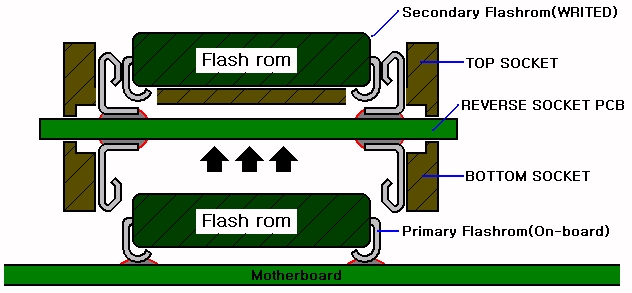
Figure.11 Remove the reverse socket from Primary flashrom after boot
f. Recover a Primary flashrom by BIOS update tool.
g. Reboot the motherboard and make sure the repair properly.
4.2. usage.2
Parts needed : FWH / LPC mode reverse socket, A secondary flashrom that is same(or compatible) with the Primary flashrom
Tools needed : small paper knife, pincette or solder iron.
Conditions of Use:
a. Use only with FWH/LPC flashrom (Wrong usage can break device)vl
b. Necessary only : 'usage.1' is not working. see usage.1.
How to use:
a. Pin-cutting must be applied to one pin of next four pin of Primary flashrom.
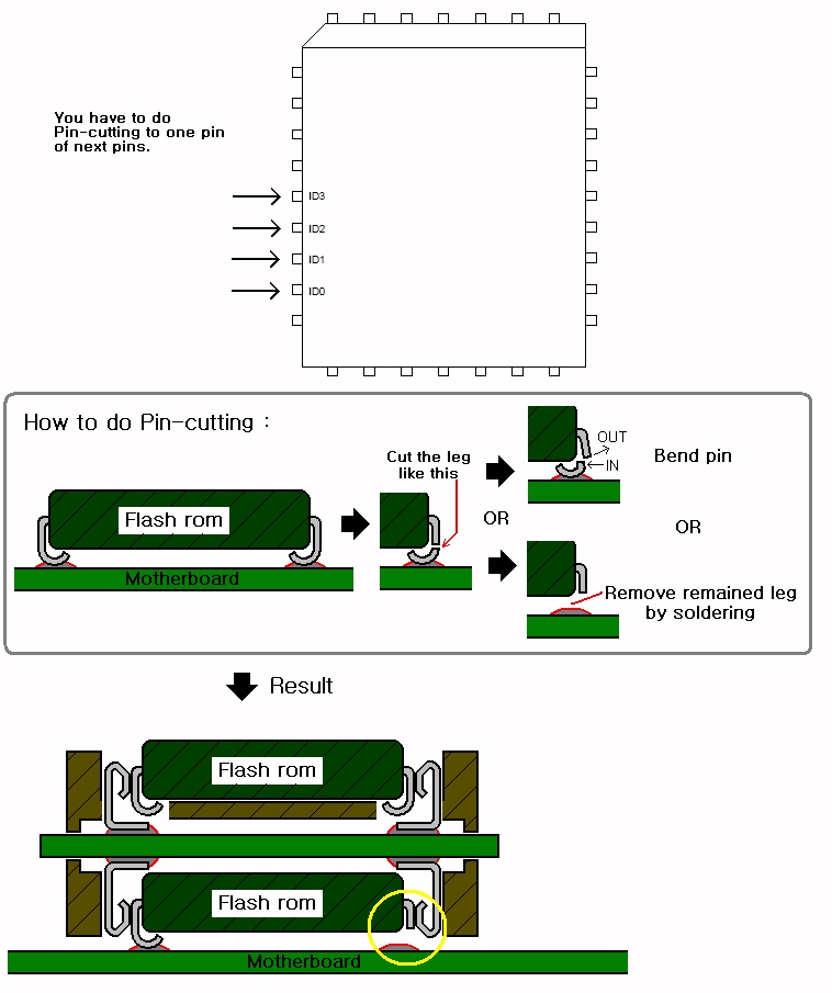
Figure.12 How to do Pin-cutting
b. Write a correct BIOS to Secondary flashrom.
c. Insert Secondary flashrom to Top socket of Reverse socket.
d. Attach Reverse scoket to Primary flashrom on motherboard.
(Warning : Primary flashrom and Secondary flashrom have same direction.
Recommended to measure a isolation between the cutted pin and GND.)
e. to enter into the OS by booting the motherboard.
(recommended to copy a BIOS update tool and BIOS file to harddisk before boot)
f. OS is fully booted and ready to run the BIOS update utility and
Remove the reverse socket from Primary flashrom.
g. Recover a Primary flashrom by BIOS update tool.
h. Reboot the motherboard and make sure the repair properly.
e. If the BIOS tool reports 'updating was success',
but motherborad does not boot, recover cutted pin by soldering.
4.3. usage.3
Parts needed : Legacy flashrom mode reverse socket, A secondary flashrom that is same(or compatible) with the Primary flashrom
Tools needed : small paper knife, pincette and solder iron.
Conditions of Use:
a. Use only with Legacy flashrom flashrom (Wrong usage can break device)
b. Pin-bypass operations and recovery operations are required.
How to use :
a. Pin-cutting must be applied to one pin of Primary flashrom in next illustration.
And remained pattern must be connected to CS point on reverse socket.
(Warning : each soldering point must be isolated electronically from near pin.)
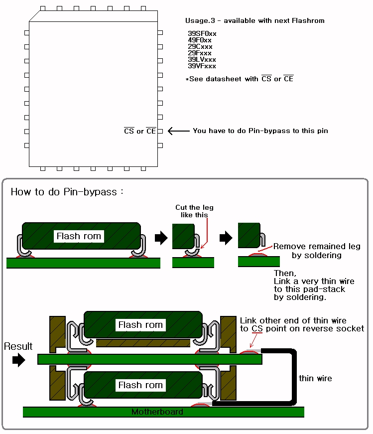
Figure.13 How to do Pin-bypass
b. Put jumper of reverse socket to 2-3 position.
c. Write a correct BIOS to Secondary flashrom.
d. Insert Secondary flashrom to Top socket of Reverse socket
e. Attach Reverse scoket to Primary flashrom on motherboard.
(Warning : Primary flashrom and Secondary flashrom have same direction.
Recommended to measure a isolation between the CS point and number 1-pin of jumper)
f. to enter into the OS by booting the motherboard.
(Recommended to copy a BIOS update tool and BIOS file to harddisk before boot.
If motherboard can't boot, check a connection of reverse socket or BIOS file.)
g. OS is fully booted and ready to run the BIOS update utility and
Move jumper to 1-2 position.
h. Recover a Primary flashrom by BIOS update tool.
i. Reboot the motherboard and make sure the repair properly.
j. If motherboard can boot, recover cutted pin with soldering.
<< Detail photo of Pin-bypass >>
Step.1 - Prepair Reverse socket.
Step.2 - Check a pin-position.
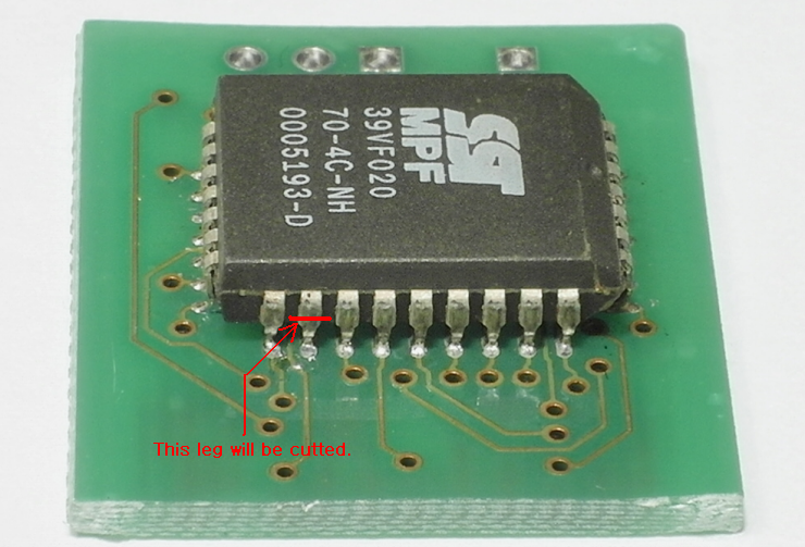
Step.3 - Cut the leg.
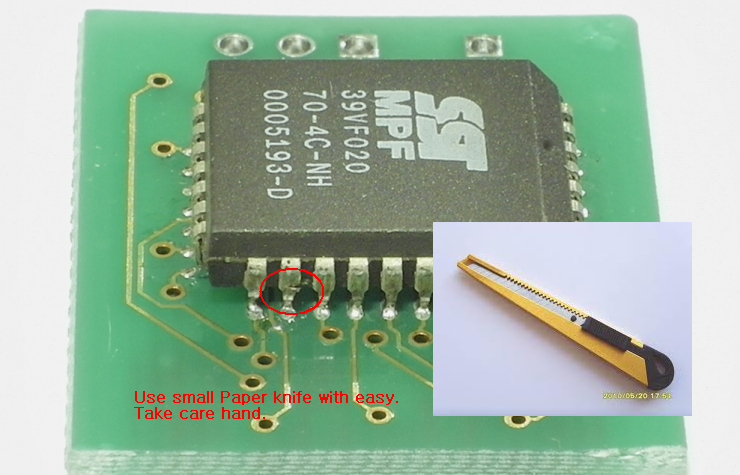
Step.4 - Cut the leg.
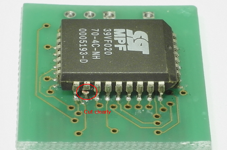
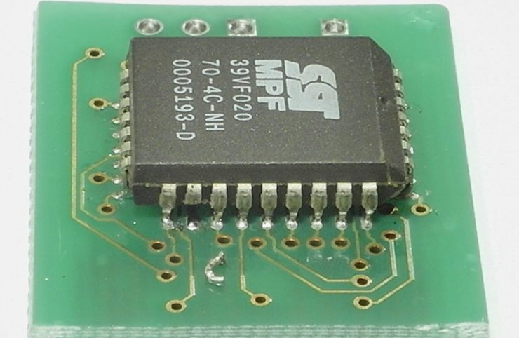
Step.5 - Remove remained piece.
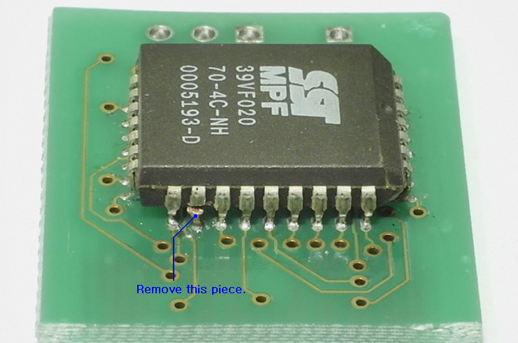
Step.6 - Remove remained piece.
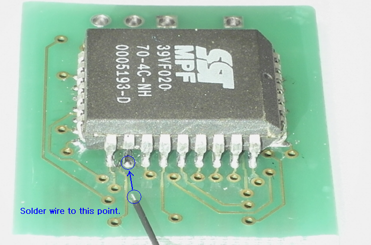
Step.7 - Solder wire to position soldered the leg.
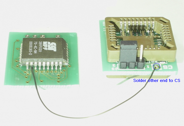
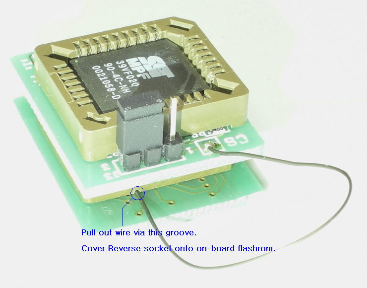
Step.8 - Solder other end of wire to CS on Reverse Socket.
Step.9 - Cover Reverse Socket to primary flashrom.


Comments can be added by Member only.